Ed's
AV Handbook
Batting Practice for the AV Professional
and primer for the novice
Chapter 4 Page 5
Video Reproduction
The TV Part 1
The TV part 1 canvases the
discontinued and waning technologies of the CRT, Plasma, and
LCD. Part 1 also outlines current home theater projector
technology. The next page, part 2, features the advanced
LED technologies of OLED, IOLED, and Micro LED.
The Relevant Past
As LCD TV dominance comes to an end, we begin with the discontinued CRT and Plasma TV technologies. All are relevant to understanding the TV.Cathode Ray Tube (CRT)
The cathode ray tube, the technology that launched television, dominated the 20th Century. CRT Color TV's key components include the cathode, the anode, two electromagnets, an electronic steering circuit, a shadow mask, and vertical sets of red, green, & blue phosphor stripes.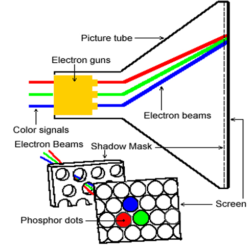
Anode/Cathode Electron Gun
Similar to an incandescent light bulb filament, three filaments in the cathode generate three distinct negative charged electrical currents. Each assigned a primary video color. The positive-charged anode draws each stream from the cathode. The combined cathode-anode produces an electron gun that generates a tight three beam stream. The RGB voltages modulate each assigned color beam.
The electron gun beam targets the
center of the shadow mask.
The mask plus screen-wide vertical sets of red,
green, & blue phosphor
stripes are adjacent to the front TV screen.
Two separate electromagnetic coils encircle the three beams. The first coil shifts the electron beams vertically up and down. The second coil sweeps the electron beams horizontally left to right. A steering circuit, directed by the horizontal & vertical synchronizing signals, controlls each electromagnetic-coil.
Modulating Electron Beams
The three modulating electron beams, guided by the electromagnetic coils, navigate the screen from left to right, top to bottom. Each beam aligns with its assigned red, green, or blue vertical phosphor stripe located behind the shadow mask. The shadow mask, a fine wire mesh of about 482 rows by 720 holes per row, allows the phosphorescent light to pass. This framed array of passing-light creates illuminated pixels that recreate an image on the screen.
Rear Projection CRT TV
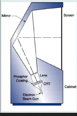
The rear projection CRT TV consisted of three
small CRTs mounted at the bottom of a large
enclosure. They were generally about 5 to 7 inches in
diameter. Each had a dedicated red, green, or blue
phosphor layer.An assembly of a magnifying lens attached to each CRT. Each assembly mated to its primary color voltage. Each magnified image converged at a large-first-surface mirror at the rear of the enclosure. The mirror redirected the magnified light through three front-mounted translucent screens.
The the Fresnel (fra-nell) screen lens and the Lenticular screen lens redirected the light. The Fresnel lens redirected the light perpendicularly from its surface. The Lenticular lens redistributed light laterally. A third protection screen shielded the Fresnel and Lenticular lenses from dust and scratches.
Plasma TV
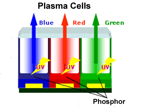
The plasma TV is a mosaic matrix array of neon/zeon gas-filled phosphor-coated glass cells; red, green, blue phosphor. The TV video processor applies voltage to each cell as dictated by the video signal. Electrically-ionized-gas emits ultraviolet light. Ultraviolet light illuminates the red, green, or blue phosphor. The illuminated array recreates the original picture.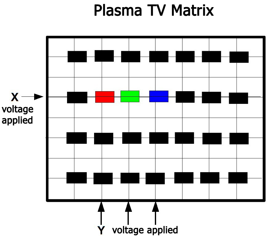
Handbook Note:
As explained on page 3, digital TV builds each video frame line by line. Plasma, LCD, OLED, IOLED, LED TV video processors hold the lines of data until they have a complete frame. They then flash the entire video frame to the screen.
LCD TV
LCD TV, a back-lit array of red,
green, or blue
color filtered liquid crystal pixels, controlled by a
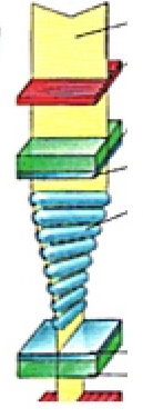
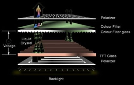
thin-film transistor (TFT) backplane. Each pixel is a string of crystals suspended in a liquid. A front crystal anchors the crystal string. Like a row of dominoes, each following crystal stands parallel but slightly off-axis. Each pixel string allows polarized light to pass until the crystal string begins to unwind and block light.
Front and rear glass plates sandwich the LCD array. The rear-plate encases the TFT grid of electrical conducting points that align behind each LCD pixel string. The electrical-conducting points control the amount of unwind. The voltage specified by the video decoder controls the conducting-point. The picture is the array-sum of the illuminated red, green, and blue filtered pixels.
LCD Back Lighting
There are two types of LCD TV backlighting -- fluorescent and LED. LED lighting consumes less energy than fluorescent lights. LED lighting is also much thinner than fluorescent lights. Thin sells TVs.
LED Back Lighting
LED backlighting consist of two types -- full-array and edge-lit. Full-array is an array of LED blocks placed behind the panel.
Edge-lit installs LEDs around the edge of the TV panel. A diffuser panel redistributes light across the entire diffuser panel.
Quantum Dot Fix
LED backlighting does not produce accurate white light. It leans toward the color blue, which distorts RGB color. Quantum dot film -- placed between the LED lighting and the LCD layer -- fixes the problem. Quantum dots are nanocrystals that illuminate when struck by LED light. A mix of red and green Q-Dots plus blue LED light produces accurate white back-light that improves video color.
There are two types of LCD TV backlighting -- fluorescent and LED. LED lighting consumes less energy than fluorescent lights. LED lighting is also much thinner than fluorescent lights. Thin sells TVs.
LED Back Lighting
LED backlighting consist of two types -- full-array and edge-lit. Full-array is an array of LED blocks placed behind the panel.
Edge-lit installs LEDs around the edge of the TV panel. A diffuser panel redistributes light across the entire diffuser panel.

Quantum Dot Fix
LED backlighting does not produce accurate white light. It leans toward the color blue, which distorts RGB color. Quantum dot film -- placed between the LED lighting and the LCD layer -- fixes the problem. Quantum dots are nanocrystals that illuminate when struck by LED light. A mix of red and green Q-Dots plus blue LED light produces accurate white back-light that improves video color.
Mini-LED Back Lighting
A mini-LED is smaller than 0.2-millimeters. It allows for more block-zones of LCD backlighting. As an example, a recent 65 inch LCD TV with more than 25,000 min-LEDs offered more than 1000 zones of backlighting. To put this in perspective, a typical 75-inch full-array backlight LCD TV may have up to 500 zones. The increase in zones improves contrast and supports HDR formats.
Handbook Notes:
1. A mini-LED is not a
micro-LED. Micro-LED is introduced on the next page.
2. Beware of advertising that obscures the term LCD in the description of an LED-back-lit LCD TV or a Quantum Dot back-lit filtered TV. It is an attempt to imply that an LCD TV is an LED or a Quantum-Dot TV. OLED, IOLED, and Micro-LED are the only real-LED TVs.
LCD Projector
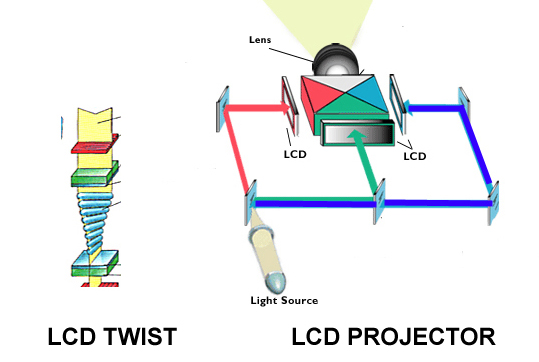
An LCD projector consists of a bright UHE-lamp targeted through polarizing mirrors that split and redirect the light with one path each to a red-filtered, green-filtered, and blue-filtered LCD mosaic chip. Each mosaic passes or blocks light per its color video instruction. The polarized mirror assembly recombines and projects the red, green, blue light through magnifying lenses to the projection screen.
DLP Projector
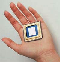
A digital light projector (DLP) features a Digital Micro-Mirror Device or DMD. The DMD is an integrated chip comprised of a mosaic matrix of microscopic mirrored pixels. Each micro-mirror is mounted on a pivot and electrostatically tilted, plus or minus ten/twelve degrees.
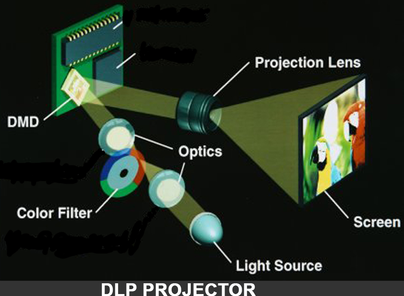
A DLP assembly begins with a bright UHE-lamp or laser light that creates a light beam directed through a spinning color wheel of red, green, and blue filters in route to the micro-mirrors of a single DMD chip. The tilt of the mirrors reflects and directs the color light into an empty enclosed area within the projector or through a magnifying lens assembly on route to a projection screen. A video digital controller coordinates each mirror's tilt with the color wheel to recreate the correct mix and amplitude of red, green, blue light and recreates the original image.
2. Beware of advertising that obscures the term LCD in the description of an LED-back-lit LCD TV or a Quantum Dot back-lit filtered TV. It is an attempt to imply that an LCD TV is an LED or a Quantum-Dot TV. OLED, IOLED, and Micro-LED are the only real-LED TVs.
Home Theater Projectors
An LCD projector consists of a bright UHE-lamp targeted through polarizing mirrors that split and redirect the light with one path each to a red-filtered, green-filtered, and blue-filtered LCD mosaic chip. Each mosaic passes or blocks light per its color video instruction. The polarized mirror assembly recombines and projects the red, green, blue light through magnifying lenses to the projection screen.
DLP Projector
A digital light projector (DLP) features a Digital Micro-Mirror Device or DMD. The DMD is an integrated chip comprised of a mosaic matrix of microscopic mirrored pixels. Each micro-mirror is mounted on a pivot and electrostatically tilted, plus or minus ten/twelve degrees.


A DLP assembly begins with a bright UHE-lamp or laser light that creates a light beam directed through a spinning color wheel of red, green, and blue filters in route to the micro-mirrors of a single DMD chip. The tilt of the mirrors reflects and directs the color light into an empty enclosed area within the projector or through a magnifying lens assembly on route to a projection screen. A video digital controller coordinates each mirror's tilt with the color wheel to recreate the correct mix and amplitude of red, green, blue light and recreates the original image.
A more costly version of the DLP projector engages three separate DMD chips and eliminates the color wheel. As an LCD projector, the light targeted through polarizing mirrors splits into three beams. Each beam directed through a red, green, or blue filtered DMD, and recombines, and projects to the screen.
LCOS Projector
LCOS projection TV is an LCD projector with a different polarizing twist. It's a bit of DLP and LCD combined. Similar to the LCD projector, the LCOS projector includes a bright light, a polarizing beam splitting mirror, and three color-filtered LCD mosaics.
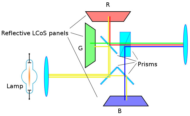
The difference is the addition of a mirrored surface behind each LCD mosaic. In this case, the light passes through the mosaic. Its mirrored surface reflects the light through the LCD mosaic chips the polarized mirrors. The polarized mirror assembly recombines and projects the light through the magnifying lenses to the projection screen.
The Laser Projector
Misused buzzwords can add confusion to any subject. Laser is the current buzzword in home theater projection.Let's clear the air with this description.
• Laser home theater projectors are Laser-lit DLP, LCD, or LCOS projectors.
• The conventional projector lamp is replaced with a laser or hybrid laser light.
The significance, they offer
brighter light, cooler operation, and longer life.
Three Lasers & 3 Chips
High-performance projectors engage three LED lasers;
• A separate red, green, and blue LED laser,
High-performance projectors engage three LED lasers;
• A separate red, green, and blue LED laser,
• Each
focused on dedicated LCD, DLP, or LCOS chip. (3 chips),
• Then
each is combined, magnified, and routed to the projection
screen.
Single Laser, Hybrid
Laser LED, & 1 Chip
More affordable single-chip
projectors reduce the light source to a single laser or a
hybrid.
Single laser models reduce the
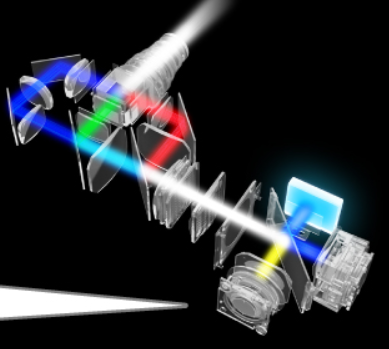
number of lasers from three to one blue laser.
The single blue laser version
splits the light into two beams, with one beam filter-converted
into yellow and green light beams.
The three beams are combined/mixed
in a lens and prism assembly to produce white light.
The Hybrid LED Laser
The hybrid laser-led light source
combines a red led with a blue laser.
The blue laser splits with one path
blue, and the other is directed through phosphor to generate a
3rd green light path.
The red led light continues as is.
In both cases, single blue or
hybrid, the light is combined/mixed to create white light.
The corrected white light
passes through .....
• A
color wheel and reflected by a DLP DMD chip.
• OR
passes through and reflected by an LCOS chip.
• OR
passes through an LCD chip.
....... And then magnified and
projected onto the screen.

A Word of Caution
You can find claims of a 3,600 LED lumen projector as twice the brightness of a 1,500 ANSI lumen projector based on the spec sheets. Many online or big-box types are unaware of the difference between the lumen and ANSI lumen. 3,600 LED lumen converts to the neighborhood of 1,500 ANSI lumen.
Additional confusion -- many manufacture-spec sheets lack
standardized testing. Therefore manufacturer versus manufacturer
spec sheet comparison is suspect. Choose a
high-performance projector based on the Foot Lambert. You can find claims of a 3,600 LED lumen projector as twice the brightness of a 1,500 ANSI lumen projector based on the spec sheets. Many online or big-box types are unaware of the difference between the lumen and ANSI lumen. 3,600 LED lumen converts to the neighborhood of 1,500 ANSI lumen.
Page 8 addresses this
issue. It outlines the lumen, LED lumen, ANSI lumen,
Foot Lamber, and Nit.
Copyright 2007 Txu1-598-288 Revised 2025
Sponsored
By

Architectural Speaker Tuning System

Architectural Speaker Tuning System
for
in-wall/ceiling custom installed speakers.
Reclaim the performance you paid for.
Site Menu
Home
Table of
Contents
Handbook Chapters
1 AV
Terms
2 AV Physics
3 Sound Reproduction
4 Video Reproduction
5 The AV System Sequence
6 The Room, Speaker, & TV
7 Acoustical Strategy - Small Room
8 Home Theater by Design
9 AV Sales Training
10 AV Business & Marketing
Contact
About
