Ed's
AV Handbook
Batting Practice for the AV Professional
and primer for the novice
Chapter
3 Page 4
Sound Reproduction
Broadcast Radio
Let's return to a time when the
first Beach Boys harmonies drifted with the breeze from
portable radios on the beaches of Southern California.
How did a Brian Wilson masterpiece of harmony travel from a
distant DJ to our radios.
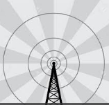
It began with a broadcaster generating electromagnetic waves, continuous modulating sparks, via their broadcast antenna. The electromagnetic waves caused electrons in our receiving radio antennas to budge, dislodge, and regenerate electromagnetic current. The modulating current, an analog of the microphones original voltage, was amplified and fed to our radio speakers. Surf's Up!
It began with a broadcaster generating electromagnetic waves, continuous modulating sparks, via their broadcast antenna. The electromagnetic waves caused electrons in our receiving radio antennas to budge, dislodge, and regenerate electromagnetic current. The modulating current, an analog of the microphones original voltage, was amplified and fed to our radio speakers. Surf's Up!

Amplitude Modulation (AM) and Frequency Modulation (FM)
The two most common methods of
radio broadcasting
AM
AM broadcasters are assigned a frequency within a limited band of the radio dial. The broadcaster's transmitter modulates the amplitude of its assigned frequency. This is analogous to changing the brightness of a distant invisible beacon of light up and down. Fast change reproduce the higher frequencies of sound. Slower change reproduce the lower frequencies. In addition, brighter is louder and the converse is less loud.
FM
FM broadcasters are also assigned a frequency in the radio band, But FM broadcasters are given room to move plus or minus of their assigned frequency. Think of the assigned frequency as a specific color of invisible light. Then as the name implies, frequency modulation shifts the frequency plus or minus of the assigned frequency, much as varying the shade of the color. Fast changes are the higher frequencies, and slower changes are the lower frequencies. Broader change is louder while the converse is less loud.
AM vs FM
AM and FM each have broadcast advantages. AM can travel longer distances than FM. But AM is sensitive to other amplitude-modulated noise such as lightning, your car's ignition, and hair dryers. FM typically avoids this interference rendering it more acceptable for music.
Audio Measurement

Accurate Standards
High fidelity audio accurately and faithfully reproduces recorded sound. It adheres to standards of accurate measurement -- frequency response, distortion, noise.Frequency Response
A frequency response test measures the uniform amplitude of the audible range of sound at the output of an audio component. A typical test measures the range from 20Hz t 20KHz. The measured result compares the amplitude to the original input. Any deviation is distortion.
Harmonic Distortion
Harmonic distortion is a measurement that feeds the input of a component from 20Hz to 20KHz in 5Hz steps. A measuring device searches for any evidence of unintended signal up to six octaves above each step. The results are summed, compared, and computed as a percentage of the original.
Signal to Noise Ratio
A signal to noise ratio is calculated by measuring a unit's output noise with no signal present. The measured noise is used to calculate a ratio between it and a fixed output reference signal.
Typical example of an
amplifier's measured specification:
-- Total continuous power = 100 watts per channel
-- Frequency response = 20Hz to 20KHz +/- 3db.
-- Total harmonic distortion (THD) = less than 0.05%
-- Signal to noise ratio (S/N) = 92db
Frequency response, harmonic distortion, and signal to noise ratios are base measurements. Select his link Rane for a comprehensive list of audio measurement.
This concept of high fidelity standards applies to any component in the playback chain. This includes electronics, speakers, interconnecting cable, and the acoustics of the listening room. However, recognize this HiFi truth. All systems that sound good measure good. But not all systems that measure good sound good. Therefore, do not forget the most sensitive measurement tool in your audio toolbox -- your ears.
< previous - 1 - 2 - 3 - 4
Copyright 2007 Txu1-598-288 Revised 2025
Site Menu
Home
Table of
Contents
Handbook Chapters
1 AV
Terms
2 AV Physics
3 Sound Reproduction
4 Video Reproduction
5 The AV System Sequence
6 The Room, Speaker, & TV
7 Acoustical Strategy - Small Room
8 Home Theater by Design
9 AV Sales Training
10 AV Business & Marketing
Contact
About

